Previous Page | Next Page | Main Noa Page
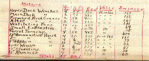
Electric plant The electric plant consists of seven generating sets, 750 incandescent lights, 4 search lights, 2 sets of signaling apparatus, 1 main switch board, 3 main distribution boards, 7 auxiliary distribution boards, together with the necessary wire, wiring accessories, molding and fixtures and the motors given in table. The seven generating sets were made by the General Electric Co. In each set there is a 50 kilowatt dynamo of multipolar type, having a capacity of 625 ampères at 80 volts, compound-wound, six-pole. The engines driving the dynamos are compound, tandem, vertical inverted; dia. Cylinders 10-1/2” x 18”; stroke 8”. The engines are designed to run with full load at 310 revolutions per minute with 110 pounds steam pressure. The bed plate is common to both engine & dynamo. The incandescent lights are of 16 and 32 candlepower, designed for 80 volts.
Each of the dynamos is connected to the main switch board, and to the equalizer board. The main switch board, containing only the panels for the dynamo and lighting and motor bus bars, distributes the current to the main distribution boards, which contain the switches of lighting circuits and motor feeders. The auxiliary distribution boards receive current from main distribution boards, and are for motors only.
[Page 49]
The ship is wired on the three wire system, with 80 volts between neutral wire and each leg, and 160 volts between outside legs. This gives a smaller amount of copper than would be necessary in the two wire system and a wider range in speed of the motors, which are generally wound for both 80 & 160 volts.
There are four search lights, two on a platform, one platform on mainmast and one on foremast. The projectors are 30 inches in diameter, hand controlled. Lamps are horizontal type with combination hand or automatic feed, and designed for a current of 75 to 90 ampères at about 50 volts. The life of the carbon is six hours, holders adjustable.
The signal apparatus is in two sets, one for each mast, of the usual Ardois type, and consists of four double signal lanterns to each set, cable connections & key boards on for’d & after bridges.
[Page 51]
Boiler designed at the Naval Academy to satisfy the specifications for the Boilers of the U.S.S. Kentucky.
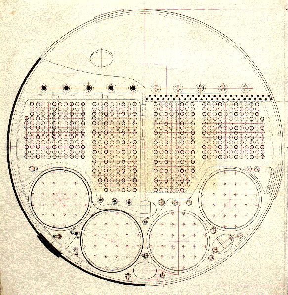
The principal differences between this design and the actual boilers on the Kentucky are (see page 45)
[Page 53]
[Page 55]
the real boilers have their combustion chambers slope down from the center line to the sides, while in my design the tops are level transversely and rounded towards the middle of the boiler. The sloping flat tops are easier and cheaper to build but are not so strong, while they must necessarily be heavier to satisfy the strength conditions. (Compare pages 45 and 47 with 51 and 53.) A defect in the construction of the Kentucky’s boilers is, that the butt straps of the longitudinal seams are not thinned down and riveted between the plates of the course next to that which they cover, but, the ends are cut off square.
[Page 67]
Description of Electric Gear in Turrets
Two fifty-horsepower electric motors are placed below the floor of each thirteen-inch turret to turn the double turret. The controller, regulating speed and direction of motors, is under the sighting hood between the two 13” guns.
[illustrator]
Each turret requires an independent generator to turn it, and any one of the seven generators may be used for the purpose. The fields of the motors and of the generators are separately excited, and therefore independent of the voltage generated by the armature of the dynamo. The field rheostat on the generator panel board is cut out and in its place another rheostat in the turret operated by the controller is used. The generator field wires being carried to the turret for this purpose.
The armature terminals of the generator are con-
[Page 69]
nected through the necessary switches directly to the armature terminals of the motors. The motors are in multiple. As the engine drives the dynamo armature at a constant speed the volts delivered by it to the motor armatures are approximately proportional to the field excitation, and consequently the speed of these armatures, and of the turret, is directly controlled by the operator in the turret.
The load causes the engine to slacken in speed.
When the motors are in motion and the controller is turned to such a position that the armatures would be driven as motors at a lower speed than that corresponding to the speed of the turret, the turret will drive the armatures, which will immediately generate current and absorb energy, bringing the turret down to the speed of the armatures when running as motors.
When the controller is placed at the “off” position the brushes of the motors are connected through a very low resistance, so that the armatures would generate large currents if revolved. This would require much expenditure of energy, which would be greatly increased by the mechanical connections, and thus electrically lock the turret. This condition does not hold unless the motor fields are excited.
The controller, in addition to operating the generator field rheostat, also sends the current to the motor armatures in the direction to give the rotation required.
There is an ammeter in front of the operator in each armature circuit, so that he may know when either motor is running under unusual load.
Below the platform on which the operator stands are the field and armature switches for cutting out the field or armature of either motor and an automatic circuit breaker which opens the armature circuit of both motors
[Page 71]
in case of an overload.
The reason for separately exciting the generator field is to cause it to respond promptly to a change of the rheostat and thus avoid the delay required in building up a self-exciting generator. The motor fields are separately excited in order to give a constant excitation which could not be obtained from the driving dynamo, as the pressure of the motor brushes will vary according to the desired speed.
Thus the person operating the rheostat controls the speed of the motor, which will remain constant at any point until this resistance is changed.
In the actual installation the same handle which controls the rheostat also controls the direction of rotation of the motor, so that the operator who is training the turret has complete command of the direction and speed of movement.
Generators. The generators are compound wound for 80 volts at the terminals, but a removable single pole, shunting switch blade is provided on the head connections board between the circuit breakers, which, when inverted, acts as a low resistance shunt across the series coil, thus allowing the latter to have a very slight effect upon the voltage of the generator, but causing the turret to start more promptly than it would if the series coil were not employed.
This shunting switch blade is removable, and should never be inserted except when operating a turret, and at all other times should be kept in the rack provided for it.
The main cables from the generator run to the double-pole double-throw switch on the panel, and are there connected to the turret feeders.