·
Previous Page | Next Page | Main Noa Page
[Page 40]
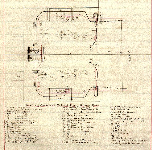
Feed water heaters In each
engine room there is a feed-water heater which is similar in construction to a
condenser. The auxiliary exhaust pipe has a by-pass valve, so that the exhaust
steam may be passed around the tubes of the heater and thence to the condenser.
The heaters are located between the feed pumps and the feed main, and the
valves are so arranged that the feed water can pass directly to the feed main
without passing through the heaters. The heating surface is 496.5 square feet
for each heater. The tubes are 1 inch in outside diameter, No. 13 B.W.S. in
thickness, and are expanded into the tube sheet. The tubes are of 70C + 29Z +
1T.
Screw propellers The
propellers are rights and lefts, of manganese-bronze, each with three
adjustable blades bent back 30 inches. They are true screws, with the pitch
adjustable from 16 to 18 feet. Each boss is secured to the shaft by two feather
keys and a wrought-steel nut screwed on and locked in place. The end of the hub
is covered with a composition cap. The blades and boss are tinned, and the outboard
sections of propeller shafts are protected by a covering of insulated copper
wire, wound tightly around the shaft casings.
Dia.
Screw, 16’9”, hub 4’4-1/2”. Length hub
3’1”, pitch 17’3”
Greatest
width blade 5’. Helicoidal area each screw 84.2 sq.ft.
Projected
area, 69.2 sq.ft., disc area, 220.35 sq.ft., Pitch dia. 1.03
Boilers There
are three double-ended and two single-ended steel boilers of the horizontal,
returns fire-tube type, all 15’8” in diameter. Each double-ended
boiler has 8, and each single-ended boiler four, corrugated furnace. The shell
of each double-ended boiler is made up of three courses of three plates each;
the longitudinal joints are treble riveted with double built straps; the
circumferential joints are lapped and treble riveted, and the heads lapped and
double riveted. The shell of each single-ended boiler is in one course of four
plates, double butt strapped and treble riveted, the joints with the head
lapped and double riveted. The joints in the fur-
[Page 41]
naces
and combustion chambers are single riveted. The heads of all boilers are curved
at the top to a radius of 3 feet 7 inches.
Furnaces The
furnaces are fitted with the ordinary cast-iron fixed grate bars. Each
double-ended boiler has four 4-1/2 inch spring safety valves, two in one case,
and each single-ended boiler, two 4-1/2 inch safety valves in one case. The
internal feed pipes are fitted with suction branches to the bottom of the
boilers, the combined feed and “circulated” water being discharged
near the water level through down-pointing branches. The auxiliary feed pumps
may also be used to circulate the water.
Tubes The
tubes in all boilers are of knobbed charcoal iron.
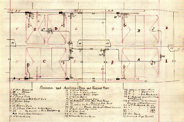
Fire-rooms The
boilers are placed fore & aft in four water-tight compartments, the two
single–ended boilers occupying the after port compartment. The passage
ways are outboard and
[Page 42]
alongside
of the boilers, with passage amidships connecting the port engine room with the
port after fire-room. There are two athwartship fire-rooms in each boiler
compartment, and eight fire-rooms in all. There are two circular smoke pipes.
The working pressure is 180 pounds per square inch.
Feed pumps There
are two main and four auxiliary feed pumps, all of the Admiralty type,
Worthington duplex, and all of the same size, 10” x 7” x 12”,
with a capacity of 400 gallons per minute. The main feed pumps are located one
in each engine room and draw water from the feed tanks and air pump suctions
and deliver to the boilers; the auxiliary feed pumps draw from the feed tanks,
the air pump suctions, the sea, the drainage system and the boilers, and
discharge into the boilers, dire main, or overboard. These pumps are located
one in each of fire rooms Nos. 3, 4, 5 & 6. The discharges of the main and
auxiliary pumps are not connected, the auxiliary fed pumps only feed through
the auxiliary feed main. In the port after fire room there is a small duplex
Worthington pump, 4-1/2” x 3” x 4” of 65 gallons per minute
capacity, for feeding the auxiliary boilers in port.
Forced draft Forced
draft is secured by the closed fire-room system. The air is supplied by eight
Sturtevant blowers, one in each fire room. The fans are driven by two-cylinder,
vertical, simple, enclosed engines with cranks at 180º.
Dia.
Steam cylinders 5”. Stroke 4”. Dia. Fan 60”, width 14”
Area
induction nozzle 1,060.7 sq.in.; eduction nozzle 2,220 sq. in.
Fire and bilge pumps
In
each engine room is a vertical, duplex Worthington pump which draws from the
sea, the bilge and the drainage system, and delivers into the fire main or
outboard. The steam cylinders are 10” and the water cylinders 7” in
diameter; stroke 12”.
Water service pumps
In
each engine room there is a vertical, duplex Worthington pump which draws from the
sea, and delivers into the water service pipes, the distiller
[Page 43]
circulating
pipes, and into the fire main. These pumps have a capacity of 400 gallons per
minute; size 10” x 7” x 12”.
Water service pumps
There
are two single acting plunger pumps on each main-engine shaft, driven by
eccentrics; one pump on each shaft is arranged to draw from the bilge and
discharge overboard; the other to draw from the sea, and discharge into the
flushing main.
Grease extractors A
grease extractor is fitted on the discharge of both main feed pumps. It is
similar in action to a Macomb strainer; the cartridge is perforated and covered
with burlap, through which the water filters. Bypass valves are fitted so that
the extractors may be overhauled without interrupting the boiler feed.
Feed tanks There
is a feed tank of 2,000 gallons capacity in each engine room. A part of the
tank is fitted as a filter, into which the water from the air pumps is
delivered. The filter has a movable cover and is provided with sponges. Each
tank has a man-hole, glass water-gage, shut-off and drain cocks. An overflow
pipe is fitted and so arranged that any water passing down it may be seen. Each
feed-pump suction is
[Page 44]
provided
with a balance valve operated by a float in the feed tank, and so arranged that
no air will enter the feed pipes.
Ash hoists In
each fire-room hatch there is a Williamson Bros. double, reversible ash hoist,
by means of which one bucked of ashes of 300 pounds (with a steam pressure of
80 pounds) can be hoisted in five seconds. The steam cylinders are 4-1/2”
in diameter, with a stroke of 4-1/2”.
Steam traps The
separators, the jackets, the main and auxiliary steam pipes, the radiators, and
all places where condensed steam can accumulate are fitted with drain pipes and
locks, or valves, and with automatic traps which discharge into the feed tanks.
The traps are provided with by-pass pipes and valves for convenience in
overhauling.
Engineer’s workshop
The
workshop is situated on the Splinter Deck, just forward of the engine rooms. It
is fitted with a vertical engine, 7” x 7”, a 24” lathe, a
14” screw cutting lathe, a shaping machine, a double-geared drilling
machine, a hand drill press, combined punch & shears, and emery wheels.
Distillers There
are two Williamson Bros. straight-tube distillers, and two evaporators, Bureau
pattern, with a combined capacity of 7,500 gallons of potable water at a
temperature of 90º F. per 24 hrs. The water service pumps are used for the
distiller circulating water. There are two distiller feed pumps of the
Worthington horizontal duplex type, two combined brine & fresh-water pumps
of the same type, and two trap pumps of the same type, except that they are
vertical. There are two filters and two water meters fitted.
Ice machine There
is an Allen dense air ice machine capable of producing the cooling effect of
one ton of ice per day; steam cylinder 9”; air compressor cyl
5-3/4”; air expander cyl. 4-3/4”; stroke 10”. The circulating
water and primer pumps are single acting, each 1-5/8” in diameter and
10” stroke. The cooling pipes connect to the ice tank, to the
refrigerating room and to the scuttlebutt.
[i]
In
each engine-room hatch is a 50” steel plate fan, driven by a 12 H.P.
electric motor, for engine-room ventilation only. For the general ventila-
[Page 45]
[illustration]
[Page 46]
tion
of the ship there are eight 50” steel plate fans located two on the berth
deck and six on the splinter deck for supplying air to the various parts of the
ship. These fans are each driven by 12 H.P. electric motor. There are also
three small exhausters driven by 3 H.P. electric motors, located two on berth
deck and one in the steering engine space, for exhausting air from the
crews’ W.C., officers W.C., and the steering engine room. All the fans
were furnished by the Sturtevant Company, and the electric driving motors by
the General Electric Company.
Telegraphs and Revolution
Indicators
A
Cory mechanical telegraph is placed in each engine room connected to
transmitters in conning tower and pilot house, and a mechanical gong in each
engine room with bell pulls in the pilot house and on the flying bridge and
near the after bridge. Mechanical tell-tales are fitted in the conning tower
and in the pilot house to show the direction of revolution of the main engines.
In each engine room there is a mechanical indicator to show the relative speed
and direction of revolution of the propellers on one dial.
Telephones and Voice Pipes
In
communications between the various parts of the ship there is a complete system
of telephones and voice pipes with call bell. All battle stations are connected
direct to the conning tower and central station. The central station is
provided for use in battle and in case of accident to conning tower.
Steering Engine On
the after platform deck there is a Williamson Bros. combined hand and steam
steering engine; cyl. 14” dia.; stroke 11”. The engine is connected
to a horizontal fore and aft shaft, on the after end of which there is a right
& left hand screw. The screw works in the crossheads, one on the starboard
and one on the port side, the rudder yoke being connected by rods to these
crossheads. With the steam gear the rudder can be put from hard over to hard
over in 20 seconds when the ship is going ahead full speed. The engine is
controlled from the conning tower and pilot
[Page 47]
[illustration and tables]
[Page 48]
house
by means of a hydraulic telemotor or by wire ropes.
Windlass The
steam windlass is in a windlass house forward of the forward turret. The engine
is reversible, double-cylinder, vertical, direct-acting, with cylinders 15
inches in diameter and a stroke of 14 inches. The windlass is fitted with two
wild cats to take the chains.
[ii]
Steam winch There
is a double cylinder steam winch in the windlass house. The cylinders are
8” dia.; stroke 8”. The winch has two drums for taking hawsers.