Previous Page | Next Page | Main Noa Page
[Page 21]
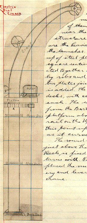
Electric Boat Cranes The boat cranes are worked by electric motors. There are four of them, two on each side, near the corners of the superstructure. The forward cranes are the heaviest, having to lift out the launches. The cranes are built up of steel plates, so as to have a square section. The plates are riveted together and strengthened by ribs and angle irons. Where two plates join a heavy butt strap is added. The cranes rest on three decks, with coned bearings on each. The section is uniform from the Berth Deck to the motor platform above the hammock rail on the Upper Deck; from this point up the crane tapers as it curves.
The round motor platform, just above the rail on the Upper Deck, is fixed to the crane and turns with. On the platform are placed the motor and all machinery and levers for operating the crane.
[Page 22]
Electric Boat Cranes Machinery
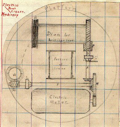
The motor lies on the platform, under the arch of the crane, and gears into a cogwheel which turns a horizontal axle (F). Near the cog (M) on this axle is a beveled wheel (N) that gears with another bevel (O), turning an axle (A) at right angles to the first axle (F). At the end of this axle (A) is a worm (P), which gears into a worm wheel on the drum fitted to hold the steel wire rope used for hoisting. At the other end of the drum is a friction break, consisting of a spring of narrowing ribbon steel (B), wound around a grooved cylinder fixed to the drum. The break is managed by pulling on a lever connected with one end of the spring, the other end being fixed.
At (C) is a joint in the axle (A). The part (D) of the axle is fixed to the wheel (C). The lever at (C), when pushed toward the drum, by means of the small rods and sliding ring at (E) expands an interior ring inside of (C) so that (D) turns with (A). When the lever is reversed the axle (D) and the drum cease to turn.
(F) is an axle having a worm at (G) which gears into a worm wheel (H) (p. 21). Below (H) is a cog (I), gearing into (K) (p. 21), a wheel perfectly fixed and not connected with the crane. (I) turns with (H). At (L) (p. 22) is a friction connection ring and
[Page 23]
lever exactly similar in construction to that at (C). When (L) is in gear the whole crane and platform turn. Thus, either drum or platform is thrown out of gear or linked up while the motor is running. The wire for the electric connection of the motor comes up the interior of the crane.
Electric Safety Break There is a new invention applied to these cranes, consisting of an electric break, which is secured by a very simple but ingenuous (sic) change of connections of the electric circuit. If a boat is suspended from the crane and motor is stopped, the safety of the boat does not depend only on the mechanical break, but, in turning off the current which stops the motor from hoisting the boat, connection is made so that the electric field operates to hold the armature rigidly in place without tending to turn it one way or allowing it to turn the other. This automatic break is strong enough to prevent the boat from falling fast, if it would not hold it entirely, and in case of carelessness in using the mechanical breaks would save the boat from a rapid drop from the crane.
[Pages 28-29]
[tables of figures for engines]
[Page 33]
[photograph of Mount Vesuvius]
Description of the Kentucky
from the Official Trip
Contract The Kentucky was built at the contract price of $2,500,000, exclusive of armor, armament, or ordnance. The time limit was three years, required speed, 16 knots for four hours, with no premium for excess, and a penalty of $100,000 per knot less than 16. If the speed fell below 15 knots the Department might reject the ship or accept her at a lower price. The contract was signed Jan. 2, 1896. Weight of machinery allowed 1,100 tons, with penalty of $500 per ton excess, and $10,000 penalty (if excess reached 5%) in addition. The general plans were furnished by the Department, details and modifications were worked out by the builders.
[Page 35]
Hull The hull, built of mild (sic) American steel, has 292 watertight compartments. All wood is fireproofed.
Main Engines The two main engines are three-cylinder, triple-expansion, vertical, inverted, direct-acting type, in separate watertight compartments, H.P. cylinders forward.
Framing: 12 wrought steel cylindrical columns, trussed and stayed diagonally, fore and aft, and athwartship. The H.P. & L.P. cylinders of one engine are secured to the corresponding cylinders of the other; the H.P. and L.P. cylinders are secured to the thwartship bulkheads.
Valves: Single-ported piston; H.P. cylinder has one valve; I.P has two; L.P. has four; each as balance piston.
Links: Double bar Stephenson type. The valve gears of the three cylinders are interchangeable. Each link has independent adjustable cut-off block, with range from .5 to .7 of stroke.
Jackets: H.P. cylinder is steam-jacked around working linings, I.P. & L.P. cylinders jacket around linings and at both ends.
Throttle valve: Double disc, balanced, stop & throttle valve, worked by a lever and adjusted by a screw.
Main steam pipes: Copper, and where over 9-1/2 inched diameter, strengthened with steel bands 6 inches apart.
Oil tank: Starboard engine-room, holds 50 gallons and supplies oil manifolds of both main engines. It is supplied from the main tanks by a Worthington duplex steam pump, and by a hand pump, and can be used either as a pressure or a gravity tank.
Main pistons: Disked steel-castings, with two packing rings & a follower.
Piston rods: Forged nickle(sic)-steel, oil-tempered, hollow; outside diameter 7-1/2”, inside 3-1/2”. A screw plug is fitted & riveted over at the upper end.
Connecting rods; caps & bolts: Forged nickle-steel, oil-tempered, 4-1/2 axial hole.
[Page 37]
Crossheads The body of the crosshead is forged on the end of the piston rod, and a manganese-bronze slipper, whose sliding faces are fitted with white metal, is bolted to its under side.
Guides The crosshead guides are of cast iron, and are made hollow for the circulation of water to keep them cool. At the top they are bolted to lugs cast on the cylinder casings, and at bottom are bolted to forged steel cross bars, secured to the engine columns. The backing guides are also of cast iron, and are bolted to flanges provided for that purpose on the go-ahead guides.
Eccentrics The eccentrics are of cast iron. Each backing eccentric is securely keyed on the shaft, and each go-ahead eccentric is secured to the corresponding backing one by through bolts in slotted holes. The eccentric straps are of composition, faced with white metal, and the eccentric rods are of forged steel.
Valve stems The I.P. and L.P. valve stems have cast steel crossheads which take hold of the link blocks directly.
Bed plates Each engine bed plate consists of three sections of steel castings.
Reversing engine: Steam float-lever, with hydraulic controlling cylinder, which can be worked by hand pump.
Turning engine: Double, inverted, simple, 7 x 5 engine, operating a worm shaft, which operates a second worm shaft & gear made to readily engage in a worm wheel secured on forward end of low pressure section of crank shaft. The turning engine shaft is squared at the end and fitted with a ratchet wrench for turning by hand.
Engine Data
Cylinders, diameter, H.P. 33-1/2”, I.P. 51”, L.P. 78”, Stroke 48”
Valves: H.P., one, diameter 19-1/2” I.P. two, 18”; L.P. four 18”
Balance pistons: H.P. 6”; I.P. & L.P. 7-1/2”. Valve stems, diameter 2-3/4”; through valves 1-7/8”
Main steam pipe, diameter 13”